VEHICLE-MOUNTED SMART WIDEBAND FREQUENCY JAMMER
1. Protecting VIP & convoys safety
Vehicle-mounted Smart RF jamming system can work on a fleet of vehicles. All radio signals within 150-250 meters around VIP convoys/stadium can be cut off. Preventing bomb detonation by radio control during VIP’s travel and providing security guarantee for VIPs and their fleet.
2. Protecting the safety for onsite EOD
The system can prevent explosives when EOD staff works on site by jamming full range RF frequency, terminates the detonation by radio controlled bomb, and provides safety for security staff and EOD staff.
3. Dealing with emergency incidents
In the event of an emergency, the system can block all existing public wireless communication, blocking messages, controlling the scene, and preventing disturbance.
4. Performance index
4.1 Main features:
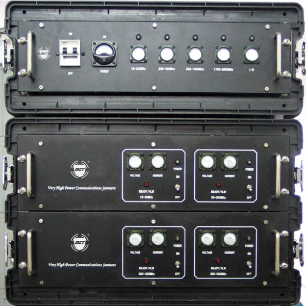
4.1.1 Sub-modules unit design can be compatible with any vehicles in need; each unit can be working independently or co-ordinately, such kind structure design can effectively improve the system reliability and flexibility.
4.1.2 The system can block and jam a variety of simple radio controlled devices and all civilian mobile communication equipments.
4.1.3 Hi-tech microprocessor-based architecture for broadband DDS driving PLL frequency synthesizer interference signal source with high efficiency AB class RF power amplifiers, combined CAN intelligent control technology used for today’s aviation & aerospace industries, making the system more stable and reliable.
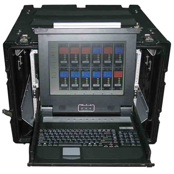
4.1.4 Well designed man-machine & user interfaces
4.1.5 Advanced ultra-wideband antenna technology applied in the vehicle makes it more concealed. Less external antenna installed on the vehicle makes the overall height of the vehicle less 2.8-3 meters, which can be driven on all traffic roads.
4.1.6 System applications: Escort convoys, fixed-point explosive searching, and fixed-point explosive defusing.
4.2 (Interfered frequency & RF output power) for Sub-module unit and interfered targets:
Note: extended frequency can be requested (based on different countries and customer needs)
4.3 (RF output power): 1500W
4.4 (Power Consumption): MAX 8000W
4.5 (Power spectrum density):
≥1.6×10⁻⁶W/Hz below 100MHz brand
≥0.5×10⁻⁶W/Hz in between 100MHz~500MHz band
≥1.4×10⁻⁶W/Hz in between 800MHz~1000MHz band
≥1.4×10⁻⁶W/Hz in between 1800MHz~2400MHz band
≥0.5×10⁻⁶W/Hz above 2400MHz bands
4.6 Frequency accuracy:+100ppm on the top end in each frequency band,
-100ppm on the low end in each frequency band
4.7 Frequency stability:±10ppm
4.8 Pn code length:No less than 256 bits / 800MHz above, other frequency band not less than 64 bits
4.9 noise modulation bandwidth: 200KHz/800MHz above the band, 50KHz / other bands
4.10 Stray inhibition:≥40dB
4.11 Harmonic control:≥40dB
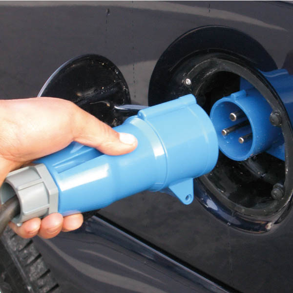
4.12 (Input Power): 26VDC、110-240VAC
4.13 (Input current): 100-200Amps@26VDC
4.14 (Operation time):Unlimited time by AC power or Generator. More than 120
minutes by internal battery DC configuration.
4.15 Battery life: ≥ 500 times in full charge and discharge cycles, or 5 years of
Storage;
Charging time: ≤ 12 hours
4.16 Environmental temperature applied:
(Operation temperatures):-30℃~+60℃;
(Start temperature):-30 ~ +65℃
Storage temperature:-40 ~ +65℃;
4.17 Standing wave antenna:≤1.5;
Anti-mismatch in antenna open circuit (Standing Wave Ratio VSWR of infinity) does not cause unrecoverable damage or performance degradation if the operation is less 30 minutes.
4.18 Gross weight: 200kg
4.19 Start up time:20 seconds
4.20 MTBF : More than 2500
4.21 Human radiation:Average radiation for people sitting in the vehicle (average
electric intensity no more than 14v/m, or continuously works, SAR value less
0.1w.kg
4.22 (Jamming Radius):
l 150-250 meter for 10-800 MHz frequency range (subject to environment change)
l 150-250 meters for above 800MHZ civilian mobile equipment (electrical level for target signal under -80dBm)
5. Antenna can be customised based on different vehicle and needs
5.1 10-30MHz whip-type on board antenna
The Antenna is designed by MCT Team, Antenna material was produced by today’s advanced – rare earth metal as the major components, which can withstand 200W continuous power output without incurring performance degradation under +80 degree. Such performance can ensure the reliability & durability for equipment radiation
5.1.1 Main electrical performance indicators
l 10MHz~30MHz;Frequency Range: 10MHz~30MHz
l 50Ω;Nominal impedance: 50Ω
l 200W;Power capacity: 200W
l VSWR: ≤1.5
l Gain: -1 - +2.5dBi
l Interface Type: N-K type plug
l Radiation pattern: horizontal Omni-directional
5.1.2 Mechanical indicators
l Antenna Length: ≤ 1.5m;
l Weight: ≤ 1.5kg;
l Mechanical properties: in line with the provisions of ;
l Environmental conditions: comply with the provisions of ;
l Life: Antenna lifespan 43,000 hours.
l Form factor: Figure
5.2 30-80MHz Antennas On-board vehicle antenna
5.2.1 The main electrical performance indicators:
l Frequency Range: 30MHz ~ 80MHz;
l Nominal Impedance: 50Ω;
l Power Capacity: 200W;
l VSWR: ≤ 1.5;
l Gain: -1 - +2.5 dBi;
l Interface Type: N-K-type plug;
l Radiation pattern: horizontal omni-directional
5.2.2 Mechanical indicators:
l Antenna Length: ≤ 1.5m;
l Weight: ≤ 1.5kg;
l Mechanical properties: in line with the provisions of ;
l Environmental conditions: comply with the provisions of ;
l Life: Antenna lifespan 43,000 hours.
l Form factor: Figure
5.3 80-300MHz Antennas On-board vehicle antenna
The antenna technical indicators for this band are as follows:
5.3.1 The main electrical performance indicators:
l Frequency Range: 80MHz ~ 300MHz;
l Nominal Impedance: 50Ω;
l Power Capacity: 100W;
l VSWR: ≤ 1.5;
l Gain: 0.5 - 2.0dBi;
l Interface Type: N-K;
l Radiation pattern: horizontal omni-directional
5.3.2 Mechanical indicators:
l Antenna Length: ≤ 0.6 m;
l Weight: ≤ 1.0kg;
l Mechanical properties: in line with the provisions of;
l Environmental conditions: comply with the provisions of ;
l Life: Antenna lifespan 43,000 hours.
5.4 300-3000MHz Vehicle mounted antenna module system
The module system is integrated over 7 antenna units, each unit isolation is around 20dB by computer assisted design and layout, through software design and careful layout makes the isolation between the various antennas 20dB above (maximizing to avoid the interaction between the antennas, and offer high gain more than 9-20 dBi for 800MHz band above).
5.4.1 The main electrical performance indicators:
l Frequency Range: 80MHz ~ 3000MHz;
l Nominal Impedance: 50Ω;
l Power Capacity: 2000W;
l Gain: 9.0 ~ 20dBi;
l VSWR: ≤ 1.5;
l Interface Type: N-K;
l Radiation Direction: Horizontal Directional
5.4.2 Mechanical indicators:
l Antenna Size: different by different system/antenna, contact us for the data
l Weight: ≤ 20kg;
l Mechanical properties: in line with the provisions of;
l Environmental conditions: comply with the provisions of ;
l Life: Antenna normal life not less than 5 years.
l Overall: According to the model and actual use to choose a different shape.
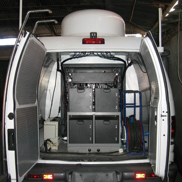
5.5 modified vehicle
5.6 vehicle applied

|